Monday, March 21, 2011

Creep Behavior of Materials

When a metal or alloy is under a constant load or stress, it may undergo progressive plastic deformation over a period of time, even though applied stress is less than the yield strength at that temperaure. This time dependent strain is called creep (above definition is taken from AMIE study material) More information is taken from Wikipdeia and shown below.


In materials science, creep is the tendency of a solid material to slowly move or deform permanently under the influence of stresses. It occurs as a result of long term exposure to high levels of stress that are below the yield strength of the material. Creep is more severe in materials that are subjected to heat for long periods, and near melting point. Creep always increases with temperature.

The rate of this deformation is a function of the material properties, exposure time, exposure temperature and the applied structural load. Depending on the magnitude of the applied stress and its duration, the deformation may become so large that a component can no longer perform its function — for example creep of a turbine blade will cause the blade to contact the casing, resulting in the failure of the blade. Creep is usually of concern to engineers and metallurgists when evaluating components that operate under high stresses or high temperatures. Creep is a deformation mechanism that may or may not constitute a failure mode. Moderate creep in concrete is sometimes welcomed because it relieves tensile stresses that might otherwise lead to cracking.

Stages of Creep
In the initial stage, or primary creep, the strain rate is relatively high, but slows with increasing strain. This is due to work hardening. The strain rate eventually reaches a minimum and becomes near constant. This is due to the balance between work hardening and annealing (thermal softening). This stage is known as secondary or steady-state creep. This stage is the most understood. The characterized "creep strain rate" typically refers to the rate in this secondary stage. Stress dependence of this rate depends on the creep mechanism. In tertiary creep, the strain rate exponentially increases with strain because of necking phenomena.

General creep equation
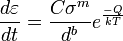
 \frac{d\varepsilon}{dt} = \frac{C\sigma^m}{d^b} e^\frac{-Q}{kT}
where {\varepsilon} is the creep strain, C is a constant dependent on the material and the particular creep mechanism, mb are exponents dependent on the creep mechanism, Q is the activation energy of the creep mechanism, σ is the applied stress, d is the grain size of the material, k is Boltzmann's constant, and T is the absolute temperature. and


Creep in materials must be taken into consideration before designing machine components which work in high temperature / high stress environments. Other components in which creep is important design consideration include Bulb filaments, Crown Glass, Metal Paper clips, ...


Don't forget to grab a copy of Material Science and Engineering book, which is essential for preparing for AMIE, Material Science.


with warm regards
AllMyPosts

Saturday, March 19, 2011

Histroy of Dutile Fractures

        Well, Hope everyone is preparing well for the Summer 2011 exams. Here are some of the cool facts about Ductile Fracture. The crack extension energy side of the Griffith equation applied only to "ideally brittle" materials. Believe me, it was not for lack of research that the materials research community failed to extend fracture theory into the very important field of ductile fracture. Some of the problems faced by Humanity due to Ductile fracture are given below:

Ships Break In Two!
This was an extremely serious problem in World War II, when over 250 ships fractured or cracked. Nineteen of these broke completely in two! Luckily, in some cases, fractures occurred in ships that were being outfitted and had never put to sea. All of the ship fractures and the two other examples that follow were in metals that were ductile, but just not tough enough.
The Great Boston Molasses Tank Disaster
One of the most famous brittle fractures was the Great Boston Molasses Tank Disaster in 1919. There was a tank of molasses, 90 ft in diameter and 50 feet high whose contents were supposed to have become rum. When the tank split, a wall of molasses advanced down the street. Many of the deaths and casualties occurred among people who were engulfed in their flats below the level of the street. There were 12 deaths and 40 injuries. Half a century later it was determined that the tank's steel was below its ductile/brittle transition temperature; the same problem as with the WWII merchant ships.
The Silver Bridge Collapse
A more recent brittle fracture disaster was the collapse of the Silver Bridge in West Virginia, in December 1967 in which 46 people perished as their cars plunged into the icy Ohio River. The National Bureau of Standards' metallurgists judged the bridge accident to be caused by stress-corrosion cracking resulting from long exposure to hydrogen sulfide vapor, H2S, from nearby paper mill digesters. The bridge failure is an example where the energy required to extend the fracture was reduced while the metal was in service.

With the benefit of 20/20 hindsight, the ship hull and molasses tank accidents occurred when the steel's energy required to extend the fracture at service temperatures was too low starting when the metal left the steel mills

The above information is taken from http://www.nhml.com/ Please do refer to them for more info. 

Factors controlling Fatigue Strength

       The fatigue limit of material is defined as stress that would cause failure after a specified number of stress reversals. The factors affecting the fatigue strength of materials and the ways of improving the fatigue strength are discussed here.

Factors controlling Fatigue strength:
  • Stress Concentration: Fatigue strength is reduced by presence of stress raisers
  • Surface Roughness: Smoother the surface finish of metal sample, higher the fatigue strength
  • Surface Treatment: Carburizing and nitriding increase fatigue life. Decarburzing lowers the fatigue life.
  • Environment: corrosive environment accelerates rate at which fatigue cracks propagate

Improving Fracture Limit
  • Good design, avoiding sharp corners, avoiding regions of stress concentration.
  • Polishing to give good finish & thereby removing surface irregularities helps
  • Short peening of metals introduces compressive stresses at surface and helps in raising the fatigue limit
  • A fine grain size improves the fatigue resistance
  • Carburzing and Nitriding will be highly helpful

The above information is taken from Material Science Study Material provided by IEI and from Material Science and Engineering by Raghavan. Don't forget to grab a copy of Material Science and Engineering book, which is essential for preparing for AMIE, Material Science.

with warm regards
AllMyPosts

Friday, March 18, 2011

Fatigue Fracture

        Fatigue fracture is a fracture that occurs when a material is subjected to cyclic loading and unloading. If the loads are above a certain threshold, microscopic cracks will begin to form at the surface. Eventually a crack will reach a critical size, and the structure will suddenly fracture.

        Rotating shafts, connecting rods, aircraft wings and leaf springs are some examples of structural and machine components that are subjected to millions of cycles of alternating stresses during service. Majority of fractures in such components is due to fatigue.

         Fatigue fracture occurs by crack propagation. The crack usually initiates at the surface of the specimen and propagates slowly at first into the interiors. At some critical stage, crack propagation becomes rapid culminating in fracture.

        The fatigue behavior can be understood from results of fatigue test, which are presented in from of S-N curves.  Samples of material are subjected to alternating stresses of different levels. The number of cycles of stress reversals N required to cause fracture is plotted against the applied stress level S. Some materials such as mild steel show a clearly defined fatigue limit. If the applied stress is below the fatigue limit, (aka Endurance Limit) the material will withstand any number of stress reversals. If materials don't show clearly defined limit, the fatigue limit is defined as stress that would cause failure after a specified number of stress reversals.

       The above info is taken from Material Science and Engineering by Raghavan and the picture shown here is taken from http://www.fea-optimization.com/. Please do refer to them for more info. 

Don't forget to grab a copy of Material Science and Engineering.

with warm regards
AllMyPosts

Monday, March 14, 2011

Griffith's Theroy: Mechanism of Brittle Fracture


      It has been observed that the stress required for a material, at which it fractures, is only a small fraction of cohesive strength. This discrepancy led Griffith to suggest that the low observed strengths were due to presence of micro-cracks, which act as the points of stress concentration. 

       According to the Griffith's criterion. the crack will propagate under the effect of a constant applied stress if an incremental increase in length produces no change in total energy of the systems. Mathematically the above criterion is explained as 
C = \sqrt{\cfrac{2E\gamma}{\pi}}


A proper explanation of the above theory is given as below by Wikipedia:

Fracture mechanics was developed during World War I by English aeronautical engineer, A. A. Griffith, to explain the failure of brittle materials. Griffith's work was motivated by two contradictory facts:
  • The stress needed to fracture bulk glass is around 100 MPa (15,000 psi).
  • The theoretical stress needed for breaking atomic bonds is approximately 10,000 MPa (1,500,000 psi).
        A theory was needed to reconcile these conflicting observations. Also, experiments on glass fibers that Griffith himself conducted suggested that the fracture stress increases as the fiber diameter decreases. Hence the uniaxial tensile strength, which had been used extensively to predict material failure before Griffith, could not be a specimen-independent material property. Griffith suggested that the low fracture strength observed in experiments, as well as the size-dependence of strength, was due to the presence of microscopic flaws in the bulk material.

      To verify the flaw hypothesis, Griffith introduced an artificial flaw in his experimental specimens. The artificial flaw was in the form of a surface crack which was much larger than other flaws in a specimen. The experiments showed that the product of the square root of the flaw length (a) and the stress at fracture (σf) was nearly constant, which is expressed by the equation:
\sigma_f\sqrt{a} \approx C
An explanation of this relation in terms of linear elasticity theory is problematic. Linear elasticity theory predicts that stress (and hence the strain) at the tip of a sharp flaw in a linear elastic material is infinite. To avoid that problem, Griffith developed a thermodynamic approach to explain the relation that he observed.

      The growth of a crack requires the creation of two new surfaces and hence an increase in the surface energy. Griffith found an expression for the constant C in terms of the surface energy of the crack by solving the elasticity problem of a finite crack in an elastic plate. Briefly, the approach was:
  • Compute the potential energy stored in a perfect specimen under an uni-axial tensile load.
  • Fix the boundary so that the applied load does no work and then introduce a crack into the specimen. The crack relaxes the stress and hence reduces the elastic energy near the crack faces. On the other hand, the crack increases the total surface energy of the specimen.
  • Compute the change in the free energy (surface energy − elastic energy) as a function of the crack length. Failure occurs when the free energy attains a peak value at a critical crack length, beyond which the free energy decreases by increasing the crack length, i.e. by causing fracture. Using this procedure, Griffith found that
C = \sqrt{\cfrac{2E\gamma}{\pi}}
where E is the Young's modulus of the material and γ is the surface energy density of the material. Assuming = 1 J/m2 gives excellent agreement of Griffith's predicted fracture stress with experimental results for glass. = 62 GPa and


The above information is taken from Wikipedia. Please do refer to them for more info. Don't forget to review this copy of Material Science and Engineering book, which has info for all the syllabus of AMIE material science.

with warm regards
AllMyPosts

Sunday, March 13, 2011

Ductile Fracture


In ductile fracture, extensive plastic deformation takes place before fracture. The terms rupture or ductile rupture describe the ultimate failure of tough ductile materials loaded in tension. Rather than cracking, the material "pulls apart," generally leaving a rough surface. In this case there is slow propagation and an absorption of a large amount energy before fracture.

Many ductile metals, especially materials with high purity, can sustain very large deformation of 50–100% or more strain before fracture under favorable loading condition and environmental condition. The strain at which the fracture happens is controlled by the purity of the materials. At room temperature, pure iron can undergo deformation up to 100% strain before breaking, while cast iron or high-carbon steels can barely sustain 3% of strain.

Because ductile rupture involves a high degree of plastic deformation, the fracture behavior of a propagating crack as modeled above changes fundamentally. Some of the energy from stress concentrations at the crack tips is dissipated by plastic deformation before the crack actually propagates.

The basic steps are: void formation, void coalescence (also known as crack formation), crack propagation, and failure, often resulting in a cup-and-cone shaped failure surface.

The steps are clearly shown in the figure given here. The above info is taken from http://www.websters-online-dictionary.org/. Please do refer to them for further info. 

Don't forget to grab a copy of Material Science and Engineering book, which is essential for preparing for AMIE, Material Science.

with warm regards
AllMyPosts

Saturday, March 12, 2011

Brittle Fracture

In brittle fracture, no apparent plastic deformation takes place before fracture. In brittle crystalline materials, fracture can occur by cleavage as the result of tensile stress acting normal to crystallographic planes with low bonding (cleavage planes). In amorphous solids, by contrast, the lack of a crystalline structure results in a conchoidal fracture, with cracks proceeding normal to the applied tension.

The theoretical strength of a crystalline material is (roughly)
\sigma_\mathrm{theoretical} = \sqrt{ \frac{E \gamma}{r_o} }
where: -
E is the Young's modulus of the material,
γ is the surface energy, and
ro is the equilibrium distance between atomic centers.
On the other hand, a crack introduces a stress concentration modeled by
\sigma_\mathrm{elliptical\ crack} = \sigma_\mathrm{applied}(1 + 2 \sqrt{ \frac{a}{\rho}}) = 2 \sigma_\mathrm{applied} \sqrt{\frac{a}{\rho}} (For sharp cracks)
where: -
σapplied is the loading stress,
a is half the length of the crack, and
ρ is the radius of curvature at the crack tip.
Putting these two equations together, we get
\sigma_\mathrm{fracture} = \sqrt{ \frac{E \gamma \rho}{4 a r_o}}.
Looking closely, we can see that sharp cracks (small ρ) and large defects (large a) both lower the fracture strength of the material.

Recently, scientists have discovered supersonic fracture, the phenomenon of crack motion faster than the speed of sound in a material. This phenomenon was recently also verified by experiment of fracture in rubber-like materials.

The above info is taken from Wikipedia and from www.ubstech.com. Please do refer to the same for further info.


Don't forget to grab a copy of Material Science and Engineering book, which is essential for preparing for AMIE, Material Science.
with warm reagards
AllMyPosts

Wednesday, March 9, 2011

Notes on Various Fractures

Hello Everyone,

Have a blessed day. Hoping your preparation is going cool unlike mine. I just thought I will share brief notes on various fractures to give a brief overview.
Brittle Fracture
     A fracture which takes place by rapid propagation of crack with a negligible deformation. In amorphous materials, the fracture is completely brittle. In crystalline materials, it occurs after small deformation.

Ductile Fracture:
     A fracture which takes place by a slow propagation of crack with appreciable plastic deformation. This type of fracture comes into play in materials which don't work harden much. 

Creep Fracture
     A fracture which takes place due to excessive creeping of materials, under steady load. Creep is exhibited in iron, nickel, copper and alloys at higher temperature.  Creep resistance may be increased by addition of certain elements such as cobalt, nickel , manganese, tungsten, ...

Fatigue Fracture:
    A fracture that occurs when a material is subjected to cyclic loading. If the loads are above a certain threshold, microscopic cracks will begin to form at the surface. Eventually a crack will reach a critical size, and the structure will suddenly fracture.

Don't forget to grab a copy of Material Science and Engineering book, which is essential for preparing for AMIE, Material Science.
with warm regards
AllMyPosts

Sunday, March 6, 2011

Fracture - Types of Fracture

      The term fracture of material may be defined as its fragmentation or separation, under action of an external force, into two or more parts. 

      Materials have some or the other weakness due to presence of submicroscopic defects (aka cracks). The cracks act as points of stress concentration. Surface roughness and surface scratches also serves as notches for stress concentration. When the stress exceeds the cohesive strength in region, cracks propagate to cause complete failure viz fracture

      Based on types of external forces, deformations and crack propagation, Fractures may be classified into the following four types:
  • Brittle Fracture
  • Ductile Fracture
  • Creep Fracture
  • Fatigue Fracture

      Fractures may also be classified as below based on metallographic examination as
  • Trans-granular (aka trans-crystalline) fracture
  • Inter-granular (aka inter-granular) fracture.
 
Don't forget to grab a copy of Material Science and Engineering book, which is essential for preparing for AMIE, Material Science.
with warm regards
AllMyPosts

Tuesday, March 1, 2011

Brittle Fracture VS Ductile Fracture

Brittle Fracture:
    • Caused due to high impact blows on the material
    • Plastic deformation is zero or very very less
    • Once crack is formed,  the crack is unstable in nature and propagates very rapidly.
    • Crack propagates nearly perpendicular to the direction of the applied stress
    • Crack often propagates by cleavage - breaking of atomic bonds along specific crystallographic planes (cleavage planes).
Ductile Fracture:
    • Caused due to tensile forces acting on the material
    • Necking can be observed i.e. excessive plastic deformation takes place
    • Crack is stable i.e. once crack is formed, it resists propagation unless further stress is applied
    • Micro-voids are formed fist, then by shear forces the crack propagates and results in fracture
Good material about about Fractures is available here & here


Don't forget to grab a copy of Material Science and Engineering book, which is essential for preparing for AMIE, Material Science.

with warm regards
AllMyPosts

Charpy and Izod Tests

I was telling about Impact hardness earlier on this blog. The Charpy and Izod tests are useful in determining the Impact hardness of the materials.


The materials with high impact hardness are ductile in nature and the materials with low impact hardness are brittle in nature.


Charpy Test:


The specimen used is 55mmx10mmx10mm in size with a V notch (making 45 degrees) as shown in figure. The specimen is held horizontally and a hammer repeatedly strikes the specimen till the specimen fails


A hammer attached to pendulum strikes the specimen when released from a height. The pendulum swings back after striking the specimen. The angle from which the pendulum is released and the angle to which the pendulum raises back after breaking the specimen are noted down and used in calculation of Impact hardness.

A picture of apparatus used is shown in the figure. The formula for calculating the energy required for breaking the specimen is given by formula
     Enegry = WR(cosα  - cosβ)

with W => weight of pendulum and hammer
        R => distance between center of gravity of pendulum to its striking edge
         α  => Initial angle from which pendulum is released
          β => The angle to which the pendulum rose after breaking the specimen


Izod Test:


Here the specimen is of size 75mmX10mmX10mm with a V notch (making 45 degrees). The specimen is held vertically and the test is performed. The entire test is similar to Charpy Test.

The pictures in the post are taken from Vhttp://www.soawe.com/time/?tag=What-is-a-charpy-test

Don't forget to grab a copy of Material Science and Engineering book, which is essential for preparing for AMIE, Material Science.

with warm regards
AllMyPosts
Related Posts Plugin for WordPress, Blogger...